What is a Cold Solder Joint and How to Fix or Prevent It
Table Of Contents
Introduction
Cold solder joints are also known as pseudo-soldering. They are a bad solder joint that is produced during PCBA or SMT. The solder joint is unreliable because it lacks good intermetallic compound (IMC) formation. This can cause serious line failures.
1. Cold Solder Joint and Why it Should Be Avoided
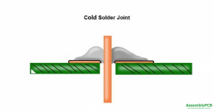
A cold solder joint forms when solder fails to melt completely (preventing proper joint formation); it has a rough, rigid, uneven surface, and is prone to cracking, failure, and increased electrical resistance–ultimately reducing the reliability of electronic assemblies.
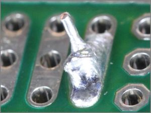
Symptoms of Cold Solder Joints:
- dull or grainy joint
- lumpy or blob-like joint
- weak or brittle connection
- circular cracks
- bulging solder point
- concave-shaped joint
Good solder joint features:
- cone-shaped fillet joint
- volcano shape
- shiny solder
- 45 °C abrupt slope
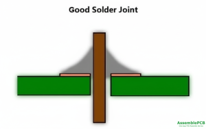
Solder should be angled 40-70 degrees away from the pin and surface of through-hole components. Heat the soldering gun to 15°C over the melting point of the solder and maintain the temperature for 45 seconds.
Surface-mounted components have no pins on the opposite side of the board. This is because they are soldered using a different process called reflow. They won’t have a concave form.
Cold solder joints are caused by a variety of soldering problems.
Disturbed Joint: When there is a disruption at the joint, before the solder paste has hardened.
Overheated Joint: This occurs when the solder does not melt correctly, which causes the flux to overheat on the board.
Insufficient Wetting: happens when the board or pin is burnt more than others.
2. Causes of Cold Solder Joint
In the next paragraphs, we will explain what causes cold solder joints.
Too little solder paste
In the solder paste printing process, either an excessively small stencil opening or insufficient squeegee pressure can lead to inadequate solder release. During the soldering stage, the insufficient solder paste at the solder joints will cause components to fail to be fully soldered,ultimately resulting in cold soldering (pseudo soldering).
Poor Quality Solder Paste
Oxidation can have an effect on solder paste, compromising its soldering performance and resulting in cold soldering joints.
Low melting points of solder paste
Low-temperature solder pastes possess a lower melting point, which causes them to melt and shed as the component temperature goes up.
Poor performance by the flux
In the course of THT (Through-Hole Technology) or SMT (Surface Mount Technology) assembly, applying flux is a necessary step prior to wave soldering—it helps eliminate oxides on the solder surfaces of components, as well as on PCB socket holes and pads. Inadequate flux performance may result in cold solder joints.
Unclean soldering surface
Electronic components are subjected to various production processes, such as surface-mounting technology (SMT) and through-hole technologies (THT). It is inevitable that during these processes, dust, metal residues, and oil can contaminate components. This can lead to cold solder joints.
Soldering iron temperature incorrect
Solder paste that is grainy will result if the temperature of the pad is too low. When the temperature is high, solder will flow, accelerating the rate of oxidation on its surface. The solder paste is then like a bead. All of these can cause non-soldering or pseudo-soldering. Temperatures recommended: Lead-free and eutectic solder at 240 °C, tin-lead eutectic solder at 215 °C.
Incorrect Soldering Time
Beginners may try to solder before the solder solidifies, then remove the tweezers holding the component, resulting in improper soldering of the component pins. Additionally, fearing damage to the components, they may quickly remove the soldering iron, which leads to insufficient soldering time to melt the solder on the joint.
Component Pin Oxidation
Oxidation on solder pads and component leads impairs their surface wettability, which in turn compromises soldering quality. If the surface of solder pads or component leads has excessive oxidation, solder fails to wet them effectively, ultimately resulting in weak solder joints or even non-soldering (cold soldering). Furthermore, these oxidative layers can create tiny air pockets on solder joint surfaces, potentially causing the joints to loosen in service.
Component pin distortion
SMD components featuring fine-pitch pins—such as Quad Flat Package (QFP) and Small Outline Package (SOP)—have a high tendency to suffer from pin damage and deformation. Such damage and deformation often lead to reduced coplanarity, as well as poor contact between certain pins and the pads, ultimately resulting in pseudo soldering.
Poor pad design
Through-holes present on pads can lead to solder loss and insufficiency;
Excessively small pad spacing, overly dense solder joints, and oversized component pads;
Mismatch between pad size and component pin size.
3. How do you fix a cold solder joint?
Soldering a cold solder joint is often as simple as re-heating it with a hot metal. Cold joints are usually the result of excess solder. The extra solder can be removed using an iron tip.
Some cold joints may require extra tools or steps. If none of the remedies above are effective, follow these simple steps:
- Use the FS-210 Brush Tip Flux Pen to flush the cold joint.
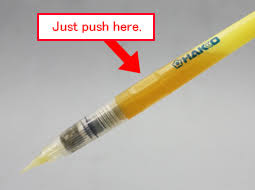
- To remelt the solder, reheat the cold solder junction using a preheater or the FV-310 Heat Gun.Continue doing this until the solder takes the shape of a traditional solder fillet. (Remember to avoid overheating.)

- Use the Techspray G3 Flux Remover to get rid of extra flux.

4. Identification Cold Solder Joint
Visual inspection or resistance tests with a multimeter can detect cold solder joints.
Visual Inspection
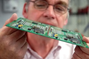
PCB solder joints are typically small, and this is especially true as board sizes continue to shrink. Therefore, visual aids such as a magnifying glass or spotlight are often required to inspect them clearly. Checking the color of the joints is the first stage in this visual inspection. This is significant since a well-formed solder joint usually looks dull.
Next, the shape of the solder joint is inspected. If the joint is distorted or lacks the expected concave profile, insufficient heating likely prevented the solder alloy from fully melting. Consequently, this can lead to increased electrical resistance, which heats the joint—potentially causing it to crack and eventually detach from the board. Subsequently, use a torch and magnifying glass to check for light penetration through the joints. If light passes through a joint, it indicates poor bonding, requiring rework.
Finally, tilt the board to inspect for joints that are partially loose from the board’s substrate. The board should also be checked for solder overflow, as this can lead to short circuits that may severely damage the board.
Multimeter Testing
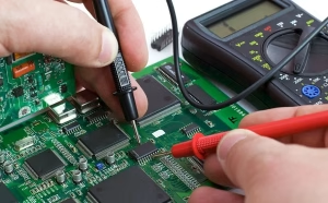
Multimeters can be used to test the resistance and continuity of a solder joint on a PCB. This test can help detect any problems at the joint. Set the resistance mode on the multimeter at 1000 to test for resistance. Connect the connectors of the testing probes to verify that the tool works correctly. Connect one terminal of the testing probe to one joint, and connect the other terminal to a different component. As long as it is not a resistance, the value should be zero. Any reading above zero could indicate a cold joint.
Connect the test terminals and put the multimeter into continuity mode to verify that the device is working. This will be confirmed by a beep. Connect the two test terminals to either end of the solder joint. There is a problem if there is no sound. The continuity test checks whether there is a constant current flow between probes. Cold solder joints will interrupt the flow.
5. Effects of Cold Solder Joint
Cold solder joints exert adverse effects that may compromise the overall functionality of a PCB. These effects primarily manifest themselves in the electrical conductivity and mechanical stability of the solder joint.
Electrical conductivity Issues
A cold solder joint that is cracked or brittle creates an unwanted air gap between the component and the pad. This, in turn, causes oxidation—with ferrous metals prone to rusting—and both of these issues significantly impair electrical conductivity. This impairment may result in either intermittent electrical contact or a complete loss of conductivity, both of which lead to reduced reliability of the PCB.
Mechanical Stability
Cold solder joints are highly susceptible to bending fatigue. Ideally, solder joints should be able to resist sustained vibration and movement. Thus, improperly bonded joints have a higher susceptibility to fatigue caused by mechanical stress, ultimately resulting in joint failure. Furthermore, erratic temperature fluctuations can inflict significant damage on cold solder connections. Over a relatively short period, such damage causes the solder joint to crack, rendering the circuit board inoperative.
6. Prevention of Cold Solder Joint
By following the instructions below, you can avoid cold solder joints.
Cleaning Components
Cleaning surfaces and components using a solvent is essential to remove any grease or contaminants that may interfere with the soldering procedure. Soldering irons are among the most important components to be cleaned on a regular basis. To prevent contamination, soldering equipment should be stored in an area that is free of dust and moisture.
Adequate Heat Applicability
Cold joints occur when solder is not melted completely. Make sure the soldering tool is pre-heated to the proper temperature and has adequate power to avoid cold junctions. For at least 45 seconds,, the peak temperature must be maintained at least 15 °C over the melting point of your alloy. Solder adhesion problems can be avoided by avoiding unreliable solder.
Adequate Amount of Solder
To ensure proper bonding, a sufficient amount of solder must be applied. A joint that is not properly soldered will dry out and crack. Solder paste should be of high quality. Avoid any vibrations or disturbances when applying solder. These can cause the paste to be spread unevenly, or even drip into areas where it shouldn’t. Soldering stations with flat surfaces can help to prevent solder flow.
7. Conclusion
Cold solder joints are the result of a PCB component soldering procedure that was not properly executed. Cold solder joint increases the electrical resistance, and this negatively affects the reliability.
A poorly formed joint can lead to reliability issues in electronic assemblies, both with regard to mechanical stability and electrical connection. Cold solder joints are easily avoided by using enough molten solder with the right heat and keeping the process clean.
8. Cold Solder Joint FAQs
1) Do cold solder joints still work?
Such issues may disrupt PCB assembly and impair its normal functionality.
2) How strong are cold solder joints?
Cold solder joints fail to create a strong, reliable connection between the components or leads they are intended to connect.
3) How many psi will a solder joint hold?
100-200 psi for basic tin-lead solders to several hundred psi for higher-strength tin-antimony and silver-bearing alloys.
4) What is wetting in soldering?
Wetting is the process which molten solder spreads, flows, and adheres to a metal surface, forming a new, strong alloy at the interface.
5) What is the white stuff on my solder joints?
It is typically an uncured or incompletely cured solder mask—a common cause of the white residue observed on solder joints.
6) What does a bad solder joint look like?
dull, rough, lumpy, or wrinkled, with potential visible cracks or rings around the component lead
7) What are the characteristics of a high-quality solder joint?
A high-quality solder joint typically exhibits a shiny, bright appearance post-soldering.
Additionally, it features a smooth, continuous surface—completely free of visible gaps, cracks, or irregularities.
Contact Us
Phone: +86-18123905375
Email: [email protected]
WhatsApp: +86-18123905375
Wechat: +86-18123905375
Free Queto
Latest Blog
Table Of Contents
Contact Us
Phone: +86-18123905375
Email: [email protected]
WhatsApp: +86-18123905375
Wechat: +86-18123905375
Free Queto


