Digital Potentiometers
1. What are Digital Potentiometers?
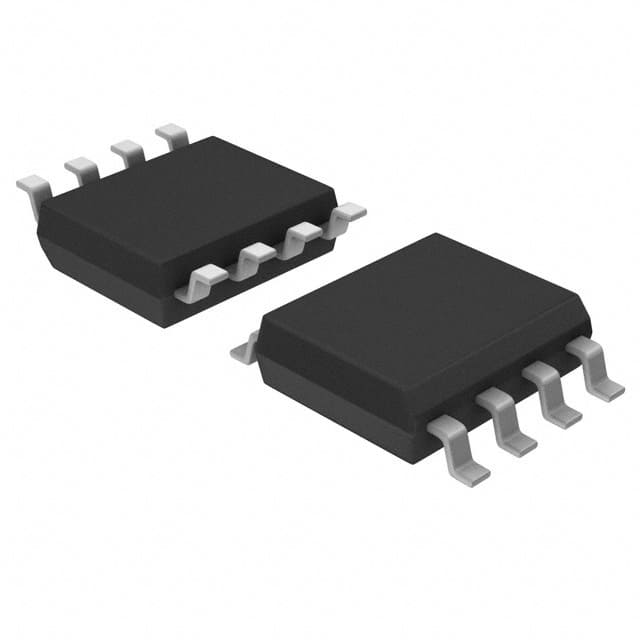
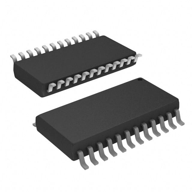
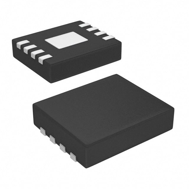
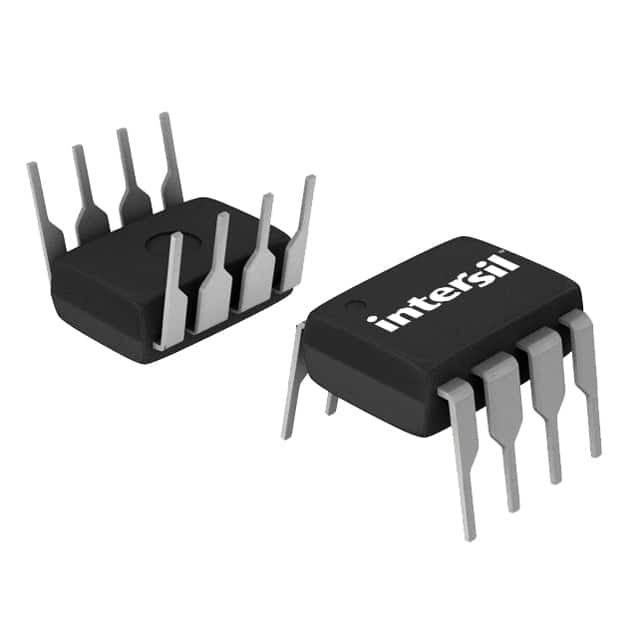
A digital potentiometer (Digipot) is an integrated circuit controlled by digital signals, which is used to simulate the resistance adjustment function of a traditional mechanical potentiometer. It is a CMOS digital-analog mixed signal processing device, which can realize dynamic adjustment of resistance value through microcontroller (such as MCU) programming.
2. What are the Core Features and Advantages of Digital Potentiometers?
Digital Control
Receive digital instructions through I²C, SPI, or up/down protocol to accurately adjust the resistance value without mechanical operation.
High Precision and Reliability
The resolution is usually 5-10 bits (32-1024 taps), 8 bits (256 levels) is the most common, and the adjustment accuracy is much higher than that of a mechanical potentiometer.
No physical contacts, anti-vibration, anti-interference, long life, and not affected by environmental contamination.
Miniaturization and Integration
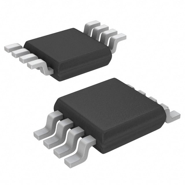
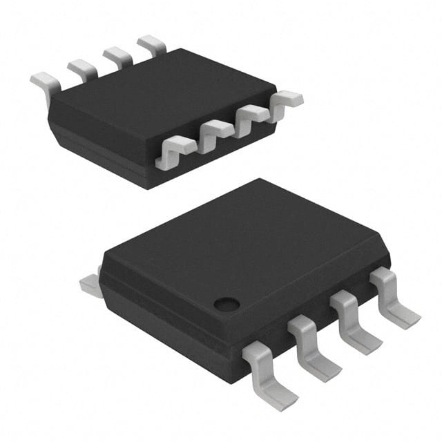
Chip-level packaging, small in size, and suitable for high-density circuit design, can be directly integrated into the analog signal processing link.
3. What is the Internal Structure and Working Principle of Digital Potentiometers?
1) Resistor Ladder Architecture:
The internal resistor array (Resistor Ladder) is used, and each tap is connected to the output end through a switch. The digital signal controls the tap position and changes the resistance ratio between the A end, the B end, and the wiper.
2) Working Mode:
Potentiometer mode (three terminals: A, B, W): Used as a voltage divider to adjust the output voltage.
Rheostat mode (two terminals: A/W or B/W): Used as an adjustable resistor.
4. What are Digital Potentiometers Used for?
Signal Conditioning: Fine-tuning amplifier gain (such as instrument amplifier), offset calibration, and small signal audio balance.
Power Management: Dynamically adjust the output voltage of the linear regulated power supply.
Dynamic Control Circuit: Adjust LED dimming current, oscillator frequency/amplitude, filter bandwidth, and differential amplifier gain.
Embedded System: Replace mechanical potentiometers to realize software control of analog circuits by MCU (such as volume adjustment of smart devices).
5. What are the Key Technical Parameters and Limitations of Digital Potentiometers?
Tap Resolution: 5 bits (32 levels) to 10 bits (1024 levels), 8 bits (256 levels) are the most common
Operating Voltage: Usually compatible with 3.3V/5V systems (such as MCP42100 supports 2.7V–5.5V)
Current Limit: Most models ≤1mA (such as MCP4XXXX series), pay attention to load design
Voltage Range Limit: The input voltage must be within the digital power supply range, and additional circuits are required when it exceeds the range
6. Comparison with Traditional Mechanical Potentiometers
|
Features |
Digital Potentiometer |
Mechanical Potentiometer |
|
Control Method |
Digital signal (MCU/logic circuit) |
Manual rotation/sliding |
|
Life and Reliability |
No mechanical wear, long life |
Contacts are prone to oxidation and wear |
|
Accuracy |
High precision, preset values can be stored |
Depends on manual adjustment, easy to introduce errors |
|
Environmental Adaptability |
Anti-vibration, humidity, temperature changes |
Sensitive to physical environment |
|
Integration |
Easy to integrate with digital systems, support bus control |
Independent physical operation required |
|
Power Handling |
Only suitable for low-power scenarios (usually ≤1W) |
Can support higher power |
7. Design Considerations for Digital Potentiometers
Current and Voltage Limits: Strictly follow the device specifications to avoid overload damage.
Cascade Expansion: Some models (such as MCP42100) support multi-module cascading to increase control channels.
Dynamic Response: The tap switching time can reach microseconds, which is suitable for real-time adjustment scenarios.
Digital potentiometers have significantly improved the flexibility and automation level of circuit control through the design concept of “placing analog devices on the bus”, and have become an ideal solution to replace mechanical potentiometers in modern electronic systems.

