
Functional Test Fixtures for Low-Volume PCBA: Files, Costs, and Acceptance Criteria
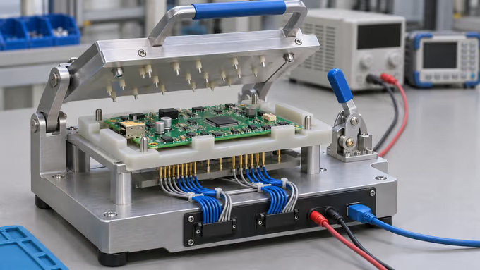
Table Of Contents
Approve the test specification before you approve the fixture. Functional test fixtures should give each PCBA a repeatable connection to the power, inputs, loads, and measurements in that specification. For a low-volume build, choose the simplest setup that can make the required checks reliably, then compare its development cost and cost per board over the expected revision life.
For a low-volume project with AssemblePCB, include the required functional checks in your assembly RFQ. Send the current hardware revision, required functions, firmware identity, and batch quantities. Ask for a defined test scope and separate allowances for fixture development, test programming, validation, and production execution where required.
Choose a Functional Test Fixture for the Required Checks
A functional test fixture locates the board and provides a repeatable electrical interface to the test station. The complete station may also need a power supply, load, instruments, communication adapter, software, and a controlled procedure. Define what each quoted item includes.
| Setup | Useful conditions | Items to confirm |
|---|---|---|
| Connector harness and bench instruments | Accessible connectors, a short sequence, and manageable operator steps. | Connector mating life, keyed connections, wiring drawing, and how readings are recorded. |
| Manual fixture with pogo pins or fixed connectors | Repeated board handling, awkward access, or several connections per unit. | Board support, probe access and force, component clearance, and replaceable wear parts. |
| Fixture with automated measurement and logging | Many test steps, defined timing, traceability, or recurring batches. | Script, instruments, licenses, operator handling, and maintenance responsibilities. |
A manual fixture can use an automated test sequence. Mechanical actuation and measurement automation are separate choices. Even ten boards may need dedicated connection hardware if a critical signal is inaccessible through normal connectors.
Assign each required behavior to a test step. A communications check should specify the messages and responses it exercises. Identify any failure modes or operating conditions left uncovered, and agree complementary inspection or electrical checks before releasing the build.
Files Needed for a PCBA Functional Test Fixture RFQ
Put one hardware revision and assembly variant in each released package. A schematic explains connectivity, while a test specification states how the powered product must respond. Include a document manifest so the fixture engineer can identify the controlling versions.
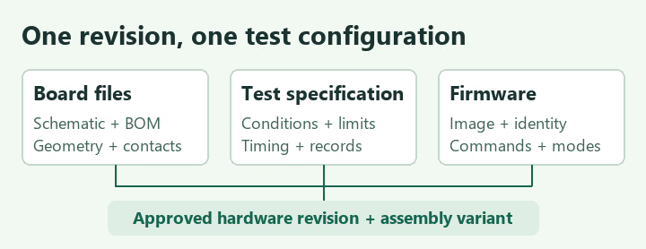
- Board and assembly files. Supply the schematic, BOM, fabrication dataset, placement file, and assembly drawings. Add STEP or dimensioned mechanical data for the populated board, connectors, locating features, and keep-outs.
- Contact map. Identify test points and connector pins, coordinates and origin, board side, signal names, grounding, and current-carrying connections. Include existing fixture or harness drawings if available.
- Behavior and limits. Define the power-up sequence, input conditions, loads, modes, measurement locations, units, settling times, pass/fail criteria, and abort conditions.
- Firmware and communication. Identify the approved image and checksum or hash, programming instructions, test-mode entry, interface settings, commands, expected responses, and exit state. State whether programming belongs in the station cycle.
- Production and records. Give pilot and repeat quantities, quantities by variant, per-unit or sampling requirements, required date, and the record format. Identify the person who can approve limits and changes.
- Reference hardware. List available verified-good boards and representative failure samples. Identify their revisions and test history, together with any customer-supplied instruments, software, cables, or loads.
If some requirements are still open, list them and ask for a separate allowance to develop the specification. That makes the engineering work visible before a fixture price is finalized.
Ready for a scope review? Include your proposed test steps with the board files and identify any fixture or software development needed. Explore our low-volume, high-mix PCB assembly service, then submit your assembly and testing requirements for review.
Write Measurable Functional Test Acceptance Criteria
For each check, document the condition, action, observation point, limit, and record. The product owner should approve these requirements before they become production pass/fail logic. NI describes how requirements, verification, and validation connect in a test system.
A worked example for a low-voltage controller
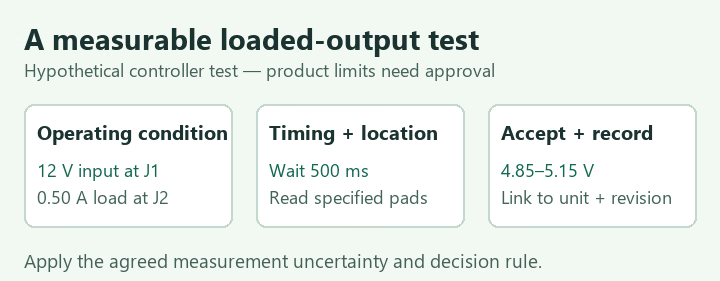
The following values are hypothetical. Assume a controller powered at 12 V DC with a regulated 5 V output and a UART diagnostic command. The product engineer has approved the conditions below for this example. Real limits must come from the actual design, operating mode, and acceptance requirements.
| Step and condition | Observation and acceptance | Record |
|---|---|---|
| Idle supply check | Apply 12.0 V ±0.1 V at J1 with a 0.8 A current limit. After the boot-complete message, enter approved idle mode, keep the external output load off, and wait 500 ms. Input current must be 20–80 mA. | J1 voltage, input current, mode response, hardware and firmware IDs. |
| Loaded output check | Command the output on. Apply a 0.50 A load at J2, wait 500 ms, then measure between the designated output and return pads. Accept 4.85–5.15 V using the agreed measurement decision rule. | Output voltage, applied load, instrument range, test-step ID. |
| Diagnostic communication | At 115200 baud, 8-N-1, send ten documented status requests. Require ten valid replies with the expected identity and status, each within 200 ms. Use no automatic retry for this example. | Reply count, returned identity, status, response time, and failed command if applicable. |
Both the lower and upper idle-current bounds have a purpose in this example. A board that never reaches the required operating state may draw unusually little current. Confirm that each limit distinguishes an intended failure condition from normal product variation.
Copy this row into your test specification
| Test ID and requirement | Inputs, mode, and load | Action and timing | Measurement point, limits, and units | Result fields and failure action |
|---|---|---|---|---|
| ________________ | ________________ | ________________ | ________________ | ________________ |
Include the measurement point and decision rule
Measure at the approved points on the PCBA. Lead and contact resistance can change the voltage reaching a loaded board. For example, 0.20 Ω total resistance at 0.50 A causes a 0.10 V drop. Check it before treating a low reading as a regulator fault.
Where supported and appropriate, remote sensing can regulate voltage at the load. Follow the instrument’s connection and compensation instructions and keep the board’s maximum ratings in view. Keysight explains the method in its remote voltage sensing note.
Agree how instrument accuracy, repeatability, and fixture effects influence the pass/fail decision. For readings near a limit, define the review or retest rule and any approved guard band. A single known-good board helps compare readings, while the product specification establishes the permitted range.
Make power sequencing and failure handling explicit
Define how the station confirms correct loading before power, applies current limits, handles a timeout, and returns the board to a safe unpowered state. Specify how stored energy is discharged before removal where applicable. Supply and interface sequencing should also prevent unintended powering through signal pins.
If a check fails, preserve the original result, identify the unit, and follow the approved hold and investigation procedure. A permitted retest should have a defined trigger and a record linked to the first attempt.
Compare Functional Test Fixture Costs Over the Revision Life
Request separate prices for specification work, fixture and interface hardware, program development, instruments or licenses, and system validation. Then ask for the recurring cost to load, connect, test, record, and unload each PCBA. Include future fixture modifications and software maintenance in the commercial discussion.
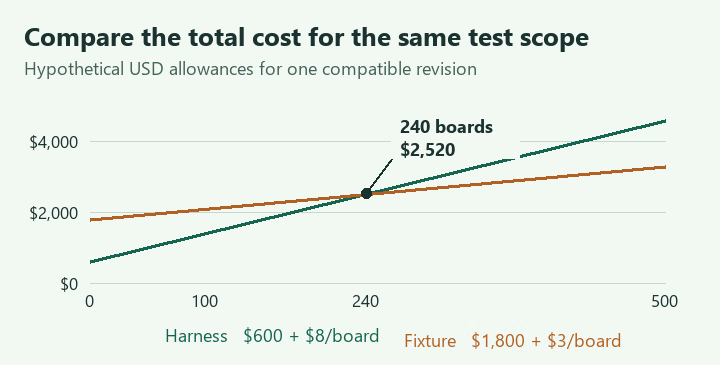
Total test cost = fixed development and setup cost + quantity × recurring test cost per board
Illustrative comparison of two equivalent test scopes
Assume both proposals implement and validate the same approved checks. All prices below are hypothetical USD allowances, including initial setup and validation. They exclude assembly, shipping, taxes, failure diagnosis, repairs, and additional retests.
| Cost item | Harness and bench procedure | Dedicated fixture and script |
|---|---|---|
| Fixed cost | $600 | $1,800 |
| Recurring allowance per board | $8 | $3 |
| Total at 100 boards | $1,400 | $2,100 |
| Total at 500 boards | $4,600 | $3,300 |
The $8 allowance could consist of five operator-minutes at $60/hour plus $3 for station use and consumables. The $3 allowance could consist of two operator-minutes at the same rate plus $1 for station use and consumables. Actual quotations should state whether test execution occupies the operator or can run unattended.
Break-even quantity = ($1,800 − $600) ÷ ($8 − $3) = 240 boards.
Both plans total $2,520 at that quantity.
Count expected units before the next fixture-affecting revision. For recurring batches, include each batch’s changeover and verification cost as well. Timing constraints, measurement access, or connection reliability may justify a dedicated fixture below the calculated crossover.
Accept the Fixture and Test Program Before Lot Release
- Check identity and fit. Confirm the supported PCBA variants, loaded-board clearance, locating features, probe map, and released wiring. Support the board near contact forces to control bending.
- Check measurement repeatability. Repeat tests with removal and reinsertion, multiple approved units, and the intended operator workflow. Compare critical readings with an independent reference method. Record instrument identity and calibration status.
- Challenge the pass/fail logic. Use approved failure samples or controlled fault simulation to verify relevant failures and boundary conditions. Verify that missing communication, a disconnected load, or a wrong firmware identity produces the specified outcome.
- Approve reporting and maintenance. Review the exported record, first-failure retention, retest linkage, probe replacement procedure, and station checks required after maintenance.
- Release the controlled package. Approve the fixture drawing, software and firmware identities, limits, operator instructions, and responsibilities. Assess affected tests again after a hardware, firmware, contact, or instrument change.
Record who owns the fixture and test code, who supplies spares, and what files transfer with the equipment. An existing customer fixture also needs a compatibility and condition review against the current board revision before production use.
Functional Test Fixture FAQs
Do small PCBA batches need an automated fixture?
Choose the connection and measurement method against the required functions, timing, and records. A keyed harness may suit a short sequence, while repeated pad access or tightly timed measurements may justify a fixture and script at low quantities.
Can I request a quotation before the test script exists?
Yes. Supply the functions, interfaces, limits already known, and the open requirements. Ask the supplier to quote specification development and validation explicitly so approval of the final scope is planned.
Who defines the acceptance limits?
The product owner normally defines or approves the limits and required operating conditions. The test engineer checks whether the proposed station can measure them repeatably and implements the approved decision rule.
Does testing every board prove complete functional coverage?
A per-unit test requirement specifies which units receive the approved sequence. List the behaviors and failure conditions each step checks so the coverage can be reviewed alongside that requirement.
Send Your PCBA Files for a Fixture Scope Review
Plan functional test fixtures around an approved behavior specification, repeatable access, and evidence that the station makes the intended decisions. Compare total cost for the expected revision life and approve the fixture, program, and records before releasing the lot.
Send AssemblePCB your board revision, schematic, BOM, firmware identity, proposed test matrix, and pilot and repeat quantities. Identify any existing fixture, reference boards, and unresolved limits. Request separate allowances for development, validation, and production testing. Use the file-upload quote form on our homepage to send your project package.
Upload PCBA Files and Request an Assembly & Test Quote
Technical reading. The linked NI guidance supports the discussion of test-system validation. The linked Keysight note explains load-lead effects and remote sensing. The test specification and cost examples in this article are illustrative engineering scenarios.
Contact Us
Phone: +86-18123905375
Email: sales@assemblepcb.com
WhatsApp: +86-18123905375
Wechat: +86-18123905375
Free Queto
Latest Blog
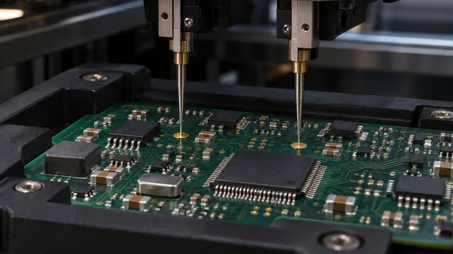
Table Of Contents
Contact Us
Phone: +86-18123905375
Email: sales@assemblepcb.com
WhatsApp: +86-18123905375
Wechat: +86-18123905375
Free Queto
